Training Course Topics
PLC Hardware Basics Training Course
- Intro
- Prerequisites
- Objectives
- What is a
PLC?
- PLCs Form Factor
- Stand Alone
- Modular
- Form Factors
Cost and Capabilities
- PLC
Chassis
- Physical
Features
- Backplane
PCB
- Module
Installation
- Chassis
Selection guide
- Allen Bradley
SLC 500 Chassis
- PLC Power
Supply
- What is a PLC
Power Supply?
- Physical
Features
- Output Power
- Sizing Allen
Bradley 1746-P1 Power Supply
- PLC
Digital Input and Output Channels
- What are Input
and Output Channels?
- Digital I/O
Module
- Operating
Voltage Range
- Allen Bradley
SLC 500 I/O Modules
- Digital I/O
Module
- Physical
Features
- Digital Input
Channels Wiring
- Sinking and
Sourcing Input Wiring
- Input Channels
Wiring Demo
- What are
transistors Output Channels?
- Transistor
Output Channels Current Rating
- Number of
Channels
- Transistor
Sinking and Sourcing Output Channels Wiring
- Output Channels
Operating Voltage Range
- Transistor
Output Channel Wiring Demonstration
- PLC Contact Output
Channels
- What Are Contact
Output Channels?
- Contact Types:
Form A, Form B, Form C.
- Contact Output
Module Internal Connection
- Voltage and
Current Rating
- Sourcing and
Sinking
- Contact Output
Channels Wiring Demonstration.
- PLC Analog Input
Channels
- What are Analog
Input Channels?
- Examples of
Practical Usage
- Types of Analog
Signals
- Examples of
Analog Input Channels Usage
- Operating
Voltage Range
- Allen Bradley
Analog Input Module
- Measurement
Accuracy
- Module
Resolution
- Voltage
Resolution Calculation
- Total Counts
Calculation
- Analog Input
Module Usage Demonstration.
- PLC Analog Output
Channels
- What are Analog
Output Channels?
- Examples of
Practical Use
- Physical
Features
- Operating
Voltage Range
- Module
Resolution
- Accuracy
- Usage
Demonstration
- Voltage
Resolution Calculation
- Counts
Calculation
- Analog I/O
Channels Wiring
- Electrical Noise
Prevention
- Cable
Shielding
- PLC
Processor
- What is a PLC
Processor?
- Examples of PLC
Processors
- Physical
Features of PLC Processors
- Indicator LEDs
and Keylock
- Communication
Ports
- Programming
Cable
- Memory Type:
ROM, RAM, EEPROM
- Memory
Structure
- Memory Capacity
Selection
- User Programs
and Firmware
- Scan
Cycle
- Scan Cycle
Analogy.
- Scan
Time
- Powering
PLCs
- Power
Requirement
- What is a
Control Transformer?
- Control
Transformer Terminal Name
- Step Down
Control Transformer
- Control
Transformer Sizing
- Volt-Amp
Rating
- PLC Rating
Label
- PLC
Power
- Control
Transformer Fuse Sizing
- Programming
PLCs
- PLC Interface
Software: RSLOGIX 500 and DirectSOFT
- PLC Program
Upload and Download
- Interface
Software Function
- RSLOGIX 500 Pro
Quick Tour
- PLC
Communication interfaces: RS232, RS485 and Ethernet
- Handheld
PLC Programmers
PLC
Programming Basics
- Training course
introduction
- PLC Memory
- Introduction
- PLC Memory Usage
- Data
Types
- Integer,
Boolean, Floating Point, counter and timer
- Data Type
Usage
- Boolean Data
Type
- Boolean Data
Type Block
- Integer Data Type
- Integer Data
Type Block
- Memory
Addressing
- Allen Bradley
Memory Addressing Convention
- RSLOGIX 500
Binary Data File
- PLC Program Overview
- Introduction
- Why some
machines require PLC programs?
- PLC Program
Inputs and Outputs
- PLC Programs
Instructions
- PLC Program
Development Software
- Ladder Logic
Programming Language
- Ladder logic
Instructions
- Reference Memory
Address
- Ladder Logic
Instruction Symbol Name
- Ladder Logic
Comments
- Ladder Logic
Rungs
- Ladder logic
Rungs State
- Ladder Logic
Branches
- PLC Program
Scan
- PLC Program
Execution
- Ladder Logic
Program VS Electrical Ladder Logic Diagram
- "RSS" RSLOGIX 500
Project Files
- RSLOGIX Micro
Starter Lite Installation
- Open RSS project
file with RSLOGIX Micro Starter Lite
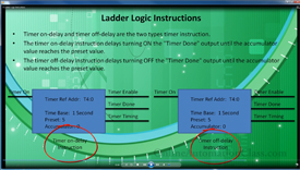
- Ladder Logic
Instructions
- Ladder Relay
Instructions Introduction
- Normally open
contact instruction
- Normally closed
contact instruction
- Output coil
instruction
- Normally open,
normal closed and output coil instruction demonstration
- Transitional
contact instruction Demonstration
- Latch output
coil instruction
- Unlatch output
coil instruction
- Latch and
unlatch output coil instruction demonstration.
- Timer
instruction
- Instruction
inputs and outputs.
- parameters
- Reset
- Analogy
- Demonstration
- Counter
instruction
- Instructions
input and outputs.
- Instructions
parameters.
- Reset
instruction.
- Analogy.Demonstration.
- Ladder Logic
Programming Tools
- Introduction
- Boolean
Expression
- Boolean
Expression to Ladder Logic Circuit Conversion
- Sum of Product
(SOP) & Product of Sum (POS) Boolean Expression
- SOP boolean
Expression Conversion Example
- POS Boolean
Expression Conversion Example
- Truth Table
Introduction
- Truth Table
Header
- Truth Table
Input Columns
- Truth Table to
Boolean Expression Conversion Example
- Karnaugh Map
Introduction
- Karnaugh Map
Vertical and Horizontal Header
- Karnaugh Map
Output Cells
- Karnaugh Map
GraCy ode
- Number of Inputs
vs Number of Output Cells
- Inputs to Output
Cell Mapping
- Karnaugh Map
Usage Example
- Karnaugh Map
Grouping Rules
- Solving Karnaugh
Maps with "Karnaugh Map Minimizer" Software
- Types of PLC
Programs
- Introduction
- Combinational
PLC Program
- Combinational
PLC Program Characteristics
- How
Combinational PLC Programs Work
- Sequential PLC
Programs
- Sequential PLC
program Characteristics
- How Sequential
PLC Programs Work
- Sequential PLC
Program Analogy
- Sequential PLC
Program Application
- Combinational
PLC Program Application
- Combinational PLC
Program Design
- Introduction
- PLC Program
Development Cycle
- Machine Logic
Specification Step
- Electrical
Schematic Drafting Step
- Design &
Implementation Step
- Expressing
Systems Logic with Truth Table
- Truth Table to
Boolean Expression Conversion
- Boolean
Expression to Ladder Logic Circuit Conversion
- Combinational
PLC Program Overview
- Testing
step
- Combination PLC
program demonstration
- Sequential PLC
Program Design
- Introduction
- Sequential PLC
Program Development Cycle
- Machine/System
Logic Specification Step
- Systems Logic
Documentation
- System I/O
Documentation
- Hardware
Schematic Drafting Step
- Design &
Implementation Step
- Sequential PLC
Program Logic Overview
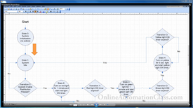
- State Diagram
Design
- State Diagram to
Ladder Logic Conversion
- Testing
Step
- Sequential PLC
Program Demonstration
Sales Policy
- 30 days money back if not satisfied.
|